

EXPLOSION DIAGRAM PARTS LIST Rotary Spool kit, Handle Kit, Matering Spool Kit, Relief Kit, They do not sold separately. HYDRAULIC FLOW CONTROL VALVE WITH RELIEF INSTRUCTION MANUAL HYDRAULIC CIRCUIT INSTALLATIONS The valve is mounted as above shown. This requires either a pressure relief valve in the system or a pump that has pressure
Get Price
Pressure relief valves mount between the pump and valve system to protect against overloads. A suitable pilot valve may be used to "vent" the balanced piston relief valve when the system does not require power. This venting unloads the pump through the relief valve at low pressure, avoiding energy waste and reducing operating costs.
Get Price
When upstream pressure falls a few psi below the set pressure, the valve will close again. Pressure Relief Valve Diagram. (1) VALVE ELEMENT (poppet valve). Most
Get Price
Pressure relief valves are used to prevent over pressurization in the hydraulic circuit. They are safeguards located close to pumps and reservoir tanks.
Get Price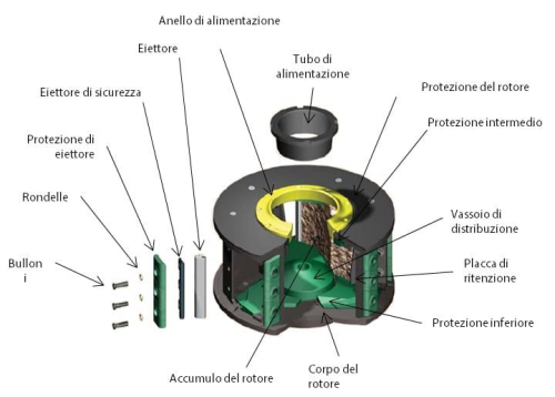
hydraulic pressure develops by resistance to pump flow. Pressure-relief valves limit the maximum pressure in a hydraulic circuit by providing an
Get Price
The most widely used type of pressure control valve is the pressure-relief valve because it is found in practically every hydraulic system. Schematic diagram of simple relief valve is shown in Fig. 1.1 and three-dimensional view is shown in Fig. 1.2. It is normally a closed valve whose function is to limit the pressure t See more
Get Price
How do relief valves work? What's the difference between cracking pressure and setting pressure? Find out by watching this Live Schematic screencast, then si
Get Price
2022/1/25 · Safety Valve A safety valve is one of the types of pressure relief valve.Its mechanism functions by inlet static pressure and it’s designed to open continuously with a pop
Get Price
Hydraulic symbology 203 Pressure Valves Circuit. Sequence valves are not much different from relief valves, and this is at once obvious by
Get Price
Relief pressure is the pressure at which the system relief valve will open and bleed flow back to the reservoir until the system pressure diminishes. Typically, the relief pressure will be set approximately 15% above the system working pressure. Thus, a system designed to operate at 2,000 PSI would have its relief valve set for 2,300 PSI.
Get Price
pressure or return line pilot line two or more functions in one unit relief valve (ec.sgra) pilot operated relief valve 3rl..) sequence valve (eg.3rs) leak-free sequence valve with external drain 9464) relief 1 unloading valve with external hydraulic pilot and internal drain (e.g.3rd) reducing valve (cc. 3rr) electrical
Get Price
Schematic diagram of simple relief valve is shown in Fig. 1.1 and three-dimensional view is shown in Fig. 1.2. It is normally a closed valve whose function is to limit the pressure to a specified maximum value by diverting pump flow back to the tank. A poppet is held seated inside the valve by a heavy spring.
Get Price
2/20 · Our video shows you the cracking pressure, the reseating pressure and what you really need to know about how a hydraulic pressure relief valve works.Relief
Get Price
Hydraulic Valves Spool Diagram Hydraulic directional valve also called hydraulic spool valve, is the most popular valve in all sorts of hydraulic systems in industrial machine, the key part of spool plays main role while the valve in operation.
Get Price
Pressure Relief Valve – Diagram , Working. Introduction. Hydraulic energy is produced as long as the prime mover (usually an electric motor) drives the pump
Get Price
Clean clogged inlet line. Clean reservoir breather vent. Repair or replace. Check for damaged pump or drive. Replace and align sheared coupling. Reverse rotation. Check position of manually-operated valves. Check electrical circuit for solenoid-operated valves. Adjust relief valve over relief valve setting.
Get Price
6/30 · Pressure reducing valves regulates system pressure for all subsequent valves, according to the adjusted pressure. Maintains a constant pressure in a secondary circuit. Includes a check valve that prevents pressure drop on secondary side. Pressure relief valves limit the maximum pressure in the hydraulic circuit.
Get Price
Hydraulic Valves Spool Diagram. Hydraulic directional valve also called hydraulic spool valve, is the most popular valve in all sorts of hydraulic systems in industrial machine, the key part of
Get Price
In addition to providing safety valve function which releases hydraulic fluid in the case of excessive pressure in the hydraulic circuit, this.
Get Price
2022/3/27 · The compound pressure relief valve consists of a small pilot operated relief valve with poppet arrangement and a main relief valve (Figure 1). It also consists of two ports, of which is one is pressure port, and the other is tank port. Pressure and tank ports are connected to the pressure line from the pump and the tank respectively.
Get Price
Maintain a constant pressure by modulating continuous, variable flow over a wide adjustment range. This drawing is not a real circuit and is
Get Price